
Blog
About
Code
Publications
Consulting
Archive
Current page
Introduction
Definitions
Trick 1 - Barycentric coordinates
Trick 2 - interpolating color
Trick 3 - Linear interpolation
Trick 4 - fan interpolation
Trick 5 - Selecting a specific face
Trick 6 - Select different values when sharing vertices
Trick 7 - Dropping triangles
Trick 101 - multi-index vertex shaders
GPU triangle tricks
In this post I list a couple of tricks that can be used in GPU shaders to bend the triangles to your will. Mostly as a reference for myself, but likely useful for others too.

Image by Dall-E2
Introduction
Code that runs on the GPU is written in shaders. Little programs that run massively parallel on your machine's graphics hardware. Programming shaders is quite different from "ordinary" programming. And requires a different kind of thinking. These tricks may help with that.
Definitions
The below explains the terms that I use in this post. For clarity I briefly explain how everything fits together.
In this post I focus on vertex-shaders and fragment-shaders, and the interaction between them. I don't consider geometry-shaders or compute-shaders. I also focus on triangles, because in the end, almost everything drawn by a GPU is based on triangles.
In a vertex shader, the vertices of the triangles are defined. Each vertex represents one corner of a triangle. The area of the triangle is called the face. Each vertex has a position (in 3D NDC), but more data can be associated with it, in the form of a float, or a vector of (up to 4) floats. These are called varyings.
The fragment shader is invoked for each fragment - each physical pixel on the face of a triangle. It's purpose is to produce the color (rgba) for the current fragment. To do this, it has access to the aforementioned varyings, but the values are interpolated over the face. They vary, hence their name.
Trick 1 - Barycentric coordinates
Let's set the stage by starting with a trick that makes clear how the interpolation of varyings really works.
One can use a vec3 as a varying to specify the corner coordinates, also see the wiki page. Over the face, the value is interpolated such that the sum of the components is always 1. If we take the first component, it is 1 in the bottom left corner, and linearly changes to zero as it approaches the opposing edge.
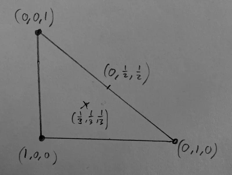
Perhaps not the simplest trick to start with, but it's interesting because it shows how interpolation of varyings really works; the GPU calculates the barycentric coordinates internally, and uses them to get the interpolated value of a varying, by multiplying the barycentric coordinates with the respective vertex-values, and adding the results.
Explicitly using these coordinates makes it possible to know the position in a face in the fragment shader. In pygfx we use this to enable sub-face picking of meshes.
Trick 2 - interpolating color
If we interpret the values in the above example as RGB values, the three corners become red, green, and blue, respectively. These colors are interpolated over the face. At the edges it goes through yellow, cyan, and magenta. At the centre it becomes gray.
One subtle difference, however, is taking into account gamma correction. You probably want to interpolate the colors in linear space, and then do the gamma correction in the fragment shader.
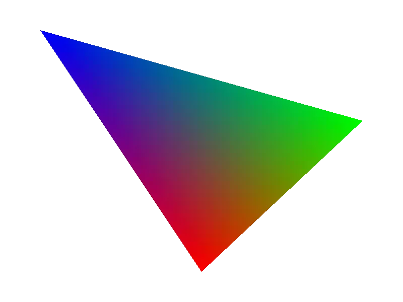
In games and modelling applications, the color value is often sampled from a texture in the vertex shader (using texture coordinates associated with the vertex), and the color is then interpolated over the face to obtain a smooth look. Sometimes the interpolation is deliberately not done, and a uniform color over the face is applied, for a retro look.
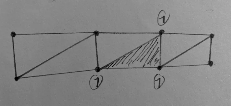
Trick 3 - Linear interpolation
Imagine interpolating between two values a and b, where one vertex gets a, and the other two vertices get value b. This interpolates the value from the corner towards the opposing edge. The isolines (where the value has the same value) are all parallel to that edge.
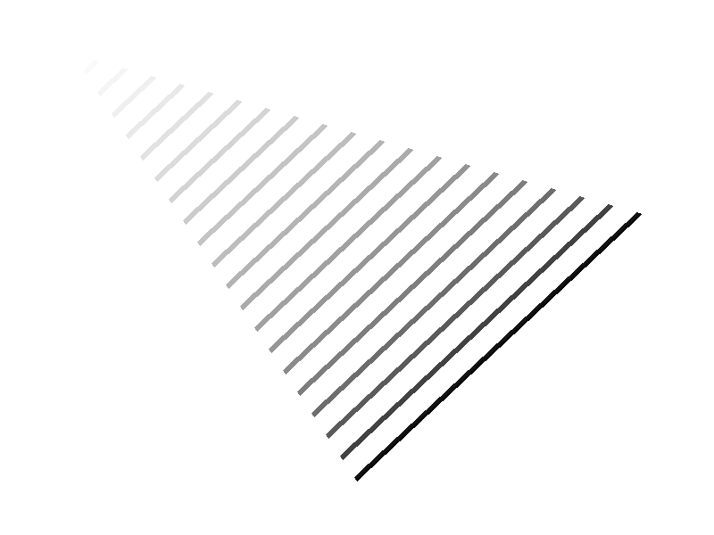
Strictly speaking this is what happens to each of the components in the barycentric coordinate's vector. In practice, this can be used to create face-coordinates for different purposes. E.g. to realise a linear and continuous value over multiple faces.
This "trick" is not particularly sophisticated, but the point it that the isolines are parallel to the opposing edge. The illustration above also shows how you may need to offset the value at the vertices so that the isolines go in the intended direction.
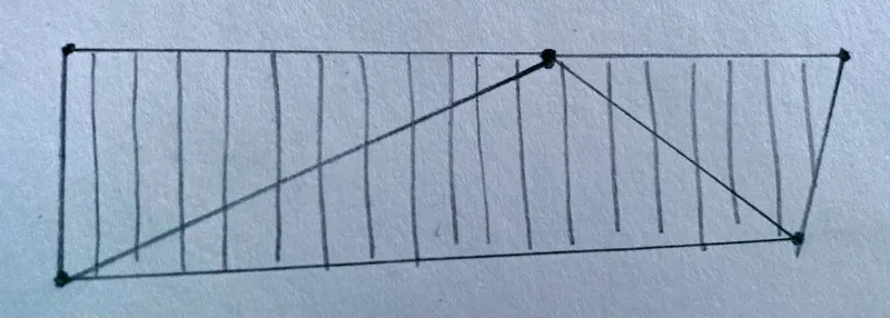
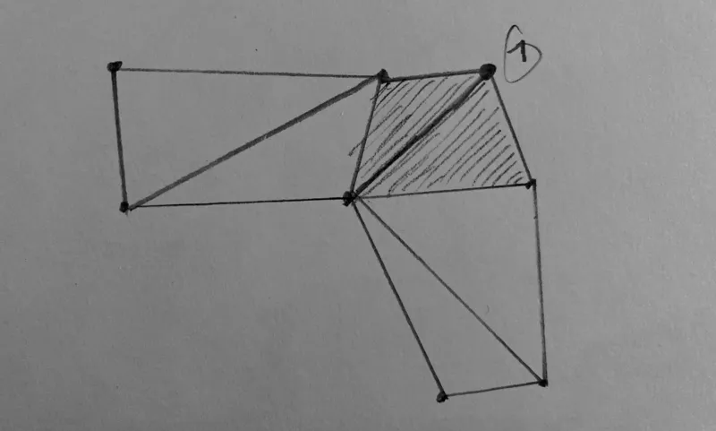
Trick 4 - fan interpolation
In some cases, one wants to interpolate a value from one vertex to another, creating a fan from the third vertex. To do this, we need to "move the third vertex out of the equation". And to do that we use another varying - let's call it the divisor - that is 1 at the two vertices that have the value of interest, and 0 at the third vertex. The principal value we're interested in must also be set to zero at the third vertex. For example, to interpolate between 104 and 117:

In the fragment shader the principal value is divided by the divisor to obtain the final value, resulting in isolines like below. One can see how the interpolation is "compressed" as one moves closer to the bottom corner.
In pygfx we use this trick to move dashes over a join (corner) in the line renderer.
Trick 5 - Selecting a specific face
In some cases (we'll get to some below) you want to know, in the fragment shader, whether you are in a triangle that requires specific action. Depending on the topology you have a few options.
a: set one vertex to 1
You use a special varying that is normally zero, but for vertices of interest you make it one. In the fragment shader you then do is_special_face = varyings.is_special != 0.0. Note that in some cases setting one vertex affects multiple triangles.
A nice feature here is that you can make the vertex either +1 or -1 and use the sign as a boolean flag for whatever additional information you need to provide to the fragment shader.
b: set three vertices to 1
You use a special varying that is normally zero, but you make it one for all three vertices of a face that requires special care. In the fragment shader you then do is_special_face = varyings.is_special == 1.0.
Trick 6 - Select different values when sharing vertices
When a vertex represents the corner of multiple faces, the value that is set for that vertex, applies to all these faces. Sometimes you don't want that. You'd wish you had a triangle_list topology instead of triangle_strip, but the latter can be so much more efficient!
A possible solution is to simply use two sets of varyings for the same value. And yet another varying to select faces as in trick 5. In the fragment shader you then select the appropriate varying bases on the "type" of face. Not particularly pretty, but it works wonders.
In the pygfx line renderer we use this to select the a different coordinate frames for joins and segments.
Trick 7 - Dropping triangles
In some use-cases you need to generate a certain number of vertices, but don't need all triangles. There are multiple ways that they can be dropped.
a: making degenerate triangles
If two vertices of a triangle have the same position, the GPU considers the triangle degenerate and does not process it further. This is a simple and effective way to drop triangles.
b: culling
A face has a certain orientation; it has a front and a back, depending on how the winding is defined. During rendering, the GPU can be told to cull (i.e. remove) the faces that have their back-side towards the viewer.
c: discarding in the fragment shader
One can discard individual fragments in the fragments shader. If you combine this with a selection method from trick 5, whole faces can be discarded. This is less efficient than the two methods above, but it may be the only possible solution.
The above tricks all apply to triangles. I would also like to list some higher-level tricks. I bumped the numbering to allow adding more simple tricks in the future.
Trick 101 - multi-index vertex shaders
The classical way that a vertex shader works is that it is invoked once per vertex, and vertex buffers are used to provide the per-vertex data that is available in the vertex shader. Although this works great for rendering meshes, it is rather restrictive for more advanced rendering techniques.
Solutions to work around these limitations include geometry shaders, compute shaders, and pre-baking the vertex buffers on the CPU. Since geometry (and compute) shaders are not always available, and doing work on the CPU is potentially slow, these solutions are rarely ideal.
In pygfx, the vertex shaders work in a different way. Firstly, we use storage buffers instead of vertex buffers. This allows the vertex shader to also query the value of neighbouring vertices. This is also the major drawback: you can only use this trick if storage buffers are available. Since pygfx is based on wgpu, this is always the case.
The vertex shader has vertex_index as its only input, and we invoke the shader a certain amount of time per "geometry data point". E.g.:
- For meshes it's 3x for each face (one triangle per face). Except for quad meshes, then it's 6x.
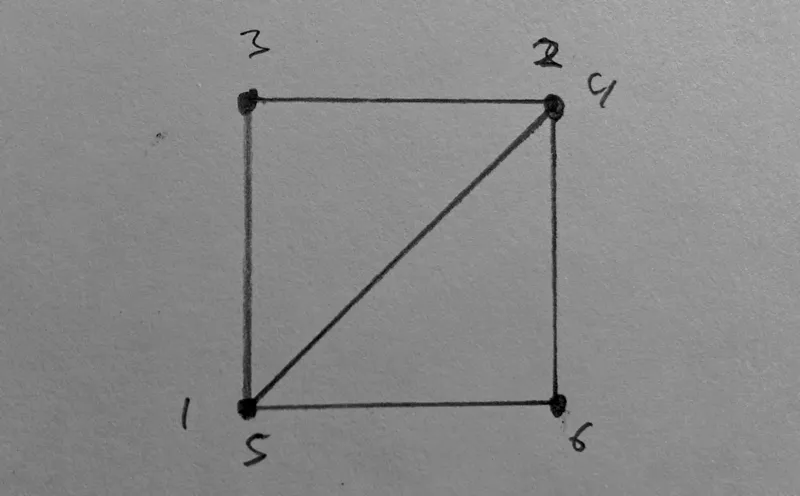
- For points/markers its 6x, to draw quads. See image below.
The vertex shader start by calculating the appropriate indices. Something like this:
// Sample from the line vertex shader in pygfx (names changed for clarity)
let index = i32(in.vertex_index);
let component_index = index / 6;
let sub_vertex_index = index % 6;
let face_index = (index + 2) / 6;
The shader then does the work to calculate the position and varyings for the current sub-vertex. This does mean there is duplicate work, because the shader is invoked multiple times per "component". However, from our observations and benchmarks, this approach is not significantly slower than using vertex buffers.