
Blog
About me
Code
Publications
Consulting
Archive
Current page
A brief overview of shaders
Setting things up
Inside the vertex shader
Taking care of perspective.
The size of our steps
How far can you go?
Inside the volume
The casting of the ray
Future improvements
Volume rendering in Vispy
We recently added volume rendering to Vispy. In this post I'll describe the method that is used, what the advantages of this method are, and possible future additions. I tried to be gentle and explain the method without giving too much boring details. Plus there is some fancy footage to demonstrate the new functionality.
The method is heavily inspired on the one used in the Visvis project. We made several improvements to it, such as ray position refinements, and the ability to render from inside the volume.
At the time of writing, the work is in a pull request, pending for merge.
Edit: the PR got merged in March 2015
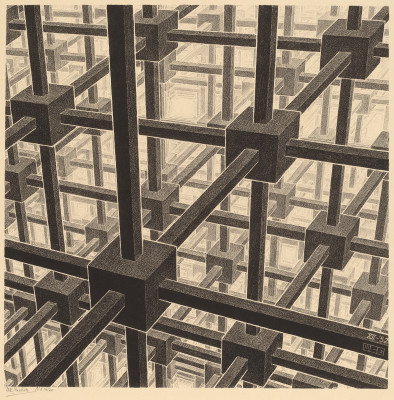
Image by Escher (public domain)
A brief overview of shaders
Before we start, let's briefly explain how executing code on the GPU works in OpenGL. To make any visualization, you need to write two programs: the vertex shader and the fragment shader. The vertex shader gets executed for each vertex, i.e. each point in the visualization. Here, you can transform the point, apply color, and prepare information for the next stage: the fragment shader. The fragment shader gets executed for each fragment, i.e. each pixel in the output image that ends up on the screen. Here, you can look up colors from a texture and do calculations to determine the final output color and depth.
There are other shaders (e.g. the geometry shader), but in Vispy we limit ourselves to the vertex and fragment shader to remain compatible with WebGL.
Image illustrating the vertex and fragment shaders.
Setting things up
In order for the shaders to work as we want, they need to be supplied with the correct information. The most elemental data are the vertices: the locations that form the base of the visualization. For our volume rendering method, we supply the locations of the 8 corners of the cube that we want to visualize. For each corner, we also supply the texture coordinate, i.e. the corresponding location inside the volume. In OpenGL terms, per-vertex data like the locations and texture coordinates are called attributes.
Further, we also supply the shaders with a texture that contains the volume data, the shape of the volume, and a parameter to determine the step size. These are called uniforms. Other uniforms that are used, but are not specific to volume rendering are the transformations to map the vertex positions to screen coordinates depending on the camera settings.
Inside the vertex shader
As is common in vertex shaders, we transform the vertex position so that it ends up in the correct position on the screen. In other words, the corners of the cube are projected onto the screen, depending on the camera state.
In order to cast a ray through the volume, we need to know the ray direction, which is influenced by the orientation of the volume, as well as the position and orientation of the camera. We calculate the ray direction in the vertex shader.
To calculate the ray direction, we map the vertex position to the view coordinate frame. This differs in a subtle way from the screen coordinate frame, because of the notion of viewboxes (i.e. subplots) in Vispy. In this coordinate frame, we transform the point a little bit forward, and then project it back to the coordinate frame local to the volume. The ray direction is defined as the difference between this new position and the original position.
This ray direction vector is thus calculated for each vertex, and then passed to the fragment shader. In OpenGL a value that is send from the vertex to the fragment shader is called a varying. The value of the ray direction as received in the fragment shader is interpolated between the vertices.
Image illustrating the calculation of the ray direction.
Taking care of perspective.
If the camera uses orthographic (i.e. not-perspective) projection, then the ray direction is the same for each vertex. This is not the case for perspective projection: the ray direction is different for each corner of the cube, and linear interpolation between these vectors will cause a wobbly effect. To mitigate this problem, we simply use more vertices. The number of vertices that is needed relates to the field of view. For typical values, a subdivision of around 10 seems sufficient.
Image illustrating the additional vertices on the front-facing planes of a cube.
The size of our steps
Although the ray direction is known, we should still scale the vector
to determine the size of the steps. We take steps of approximately the
voxel size, multiplied with the user settable u_relative_step_size.
Higher values will typically yield prettier results, at the cost of
performance. Later in this post we discuss a trick to get good
results with relatively large steps. The main point is that we should
not completely step over voxels, because we might miss important
structure in the volume.
How far can you go?
Now that the ray casting vector is fully determined, there is but one thing to calculate before we can step through the volume inside the fragment shader: the number of steps.
There are several approaches for calculating the number of steps. A common method is to first render the backfaces to a texture (using an FBO), thereby creating a depth map that you can use during raycasting. Our method uses a more direct approach, which does not need a FBO, and probably has a better performance (I haven't any hard data on that though).
In the fragment shader, we have a texture coordinate which corresponds to the start location of the ray (on the edge of the cuboid). This is the starting point of the ray casting. We also know the direction through the volume. We calculate the distance from this starting point to each of the six planes (i.e. faces) of the volume, using a simple mathematical formula. This formula yields a negative distance if the plane is behind the vector. The number of steps is the minimum distance, discarding negative values.
We apply a trick by defining all planes a tiny bit to the outside, so that the plane that the start position is on will be behind the ray, leading to a distance of -1, and will thus be discarded.
Further, it's important to set the wrapping property of the texture to clamp (and not repeat), so that moving half a step outside the volume won't yield wrong results.
Video showing the number of steps encoded in color (brighter is more steps)
Inside the volume
A nice feature of this method is that you can put the camera inside the volume. Instead of taking the front-facing planes of the volume as a starting point, we use the back-facing planes of the volume and the front-facing planes are discarded. In effect, the volume can be rendered also from inside the volume, and it should be easier to render other objects inside the volume (e.g. segmentation results).
To allow this, however, we need to take the clipping plane of the camera into account. So in addition to the six planes that we test to determine the number of steps, we also test the plane that is at the camera position. You can see in the video above how the number of steps decreases (i.e. the color becomes less bright) as the camera moves further inside the volume.
The casting of the ray
From here the casting of the ray is relatively simple. In a loop from zero
to nsteps, we increase our texture coordinates with the ray vector.
At each iteration we sample the value from the 3D texture and process
it. The kind of processing that we apply depends on the rendering style that
is used. In maximum intensity projection (MIP) we simply remember the highest
intensity. In isosurface rendering, we cast the ray until the intensity
above a certain threshold value, and then do the lighting calculations.
In a post-processing stage, we re-cast a fraction of the ray in very small steps around the depth of interest. Thereby we refine the ray, such that we can do with relatively large step sizes and still get consistent and pretty results.
Video showing the volume rendering in action
Future improvements
There are several ideas to bring the implementation further:
- More render styles. See e.g. this visvis example
- Colormapping, to give these gray MIP's a more appealing and useful appearance.
- Allowing for anisotropic data, useful for medical images.
- Use a 2D texture to store the 3D data, so that our volume rendering can be used in WebGL, e.g. in the IPython notebook.
- Adopt techniques like shadows (see the upcoming WebGL Insights for an example).
- Use adaptive step sizes to realize increased performance.
- The use of octrees allows rendering massive datasets in realtime.